Convert user mass, operating speed and linkage forces into a design case.
Cross-trainer shaft design and validation.
I designed the main stepped shaft for an elliptical cross-trainer and used finite element analysis to check its stress and deformation under the specified operating load.
ProblemTransfer flywheel and linkage loads while maintaining alignment
ApproachHand calculations, detailed features and static FEA
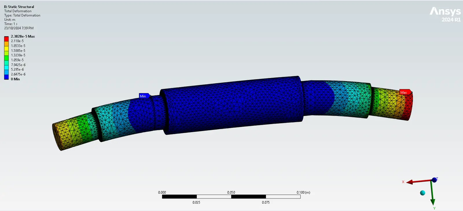
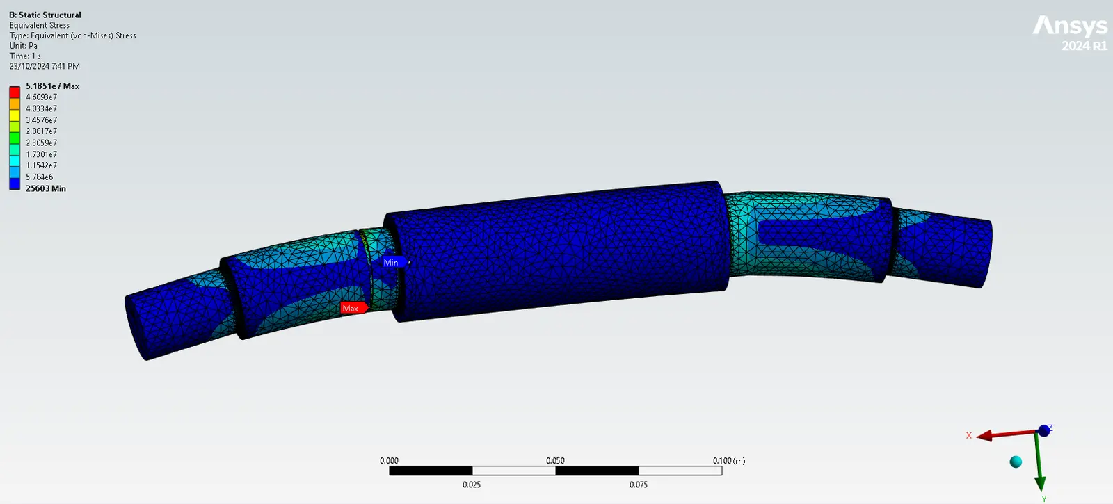
Result51.85 MPa maximum stress and 23.8 µm deformation
My roleShaft sizing, specification, material selection and ANSYS analysis
Problem
What did the shaft need to do?
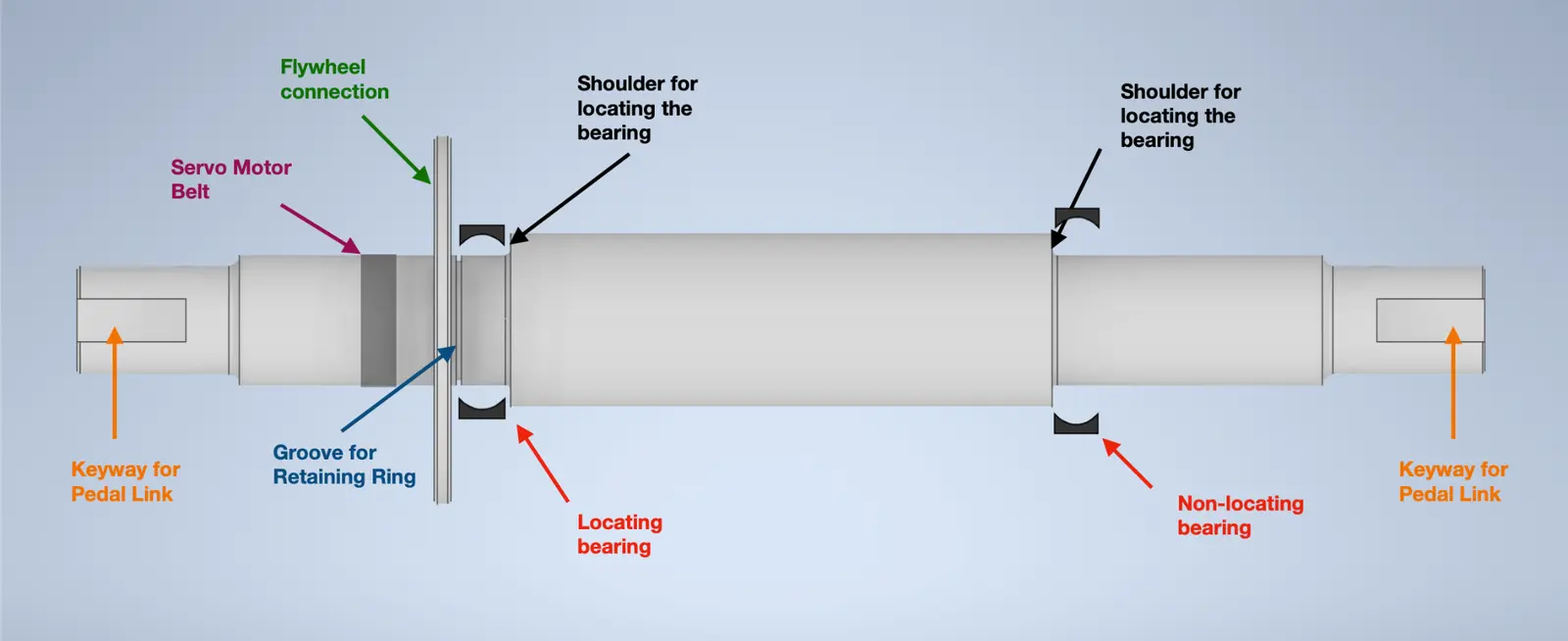
The shaft had to transfer the flywheel and linkage loads for a 110 kg user operating at 60 rpm, while supporting bearing alignment and a 15,000-hour design-life target. It also needed practical keyways, shoulders, bearing seats and retaining features.
Design problem
Size a manufacturable shaft, then show that the complete geometry—not only an idealised diameter—could carry the reported static load case without excessive stress or movement.
Approach
From design calculations to a finite element model.
Estimate critical diameters for combined bending and torsion.
Specify shoulders, keyways, bearing seats, fillets, grooves and tolerances.
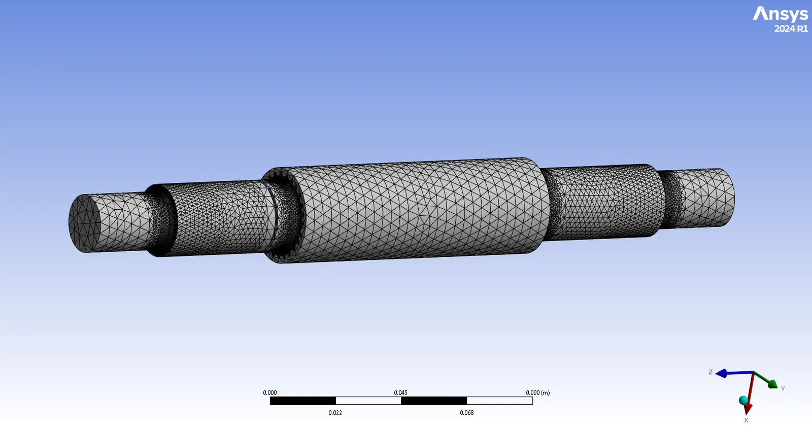
Apply material, supports and loads, refine the mesh, then review stress and deformation.
- Selected AISI 4340 steel, quenched and tempered at 650°C, using the strength and fatigue requirements of the application.
- Used local mesh refinement of about 0.5 mm around steps and shoulders, with a coarser 4 mm mesh elsewhere.
- Checked the stress contour as well as the maximum value so that local stress raisers were not hidden by a single number.
Result
What the model showed.
The reported maximum von Mises stress was well below the 834 MPa yield strength used for AISI 4340, and predicted movement remained small at the component scale. This supported the design for the stated static case, but did not prove fatigue life or performance in every operating condition.
51.85 MPamaximum von Mises stress
23.8 µmmaximum total deformation
834 MPayield strength used for comparison
Design decision
Low-stress regions suggested that the shaft may have been conservatively sized. Shoulders and keyway transitions remained the priority areas for fillet and fatigue review.
Reflection
What I learned.
I learned that FEA is most useful when it follows clear engineering assumptions. A polished contour is not evidence by itself; loads, constraints, material data and mesh choices determine what the result means.
- I improved at translating a broad product requirement into dimensions, interfaces and a load case.
- I learned to connect hand calculations with a more detailed numerical model.
- I became more careful about stress concentrations at steps, grooves and keyways.
- I learned to report what a model supports without overstating it.
Limitations
Where the work could have been stronger.
These were the main weaknesses of the analysis and the areas I would address in a later design stage.
- Static analysis only: fatigue, start-up, impact and misuse cases were not fully modelled.
- Mesh evidence: local refinement was used, but a complete mesh-convergence study was not presented.
- Boundary conditions: the bearing, contact and support behaviour was simplified.
- No physical correlation: strain or deflection was not checked on a loaded prototype.
- Design efficiency: the large margin to yield suggests that mass and material use could be reconsidered.
What I would change
Add fatigue and sensitivity studies, test alternative support assumptions, complete formal mesh convergence, and compare the model with strain-gauge or deflection measurements on a prototype.